Home » Separators » Alfa Laval Separators »
Alfa Laval Brew 450 Separator
Introduction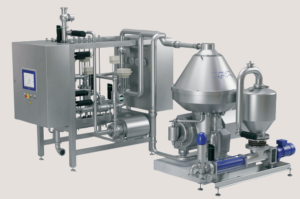
For more than 100 years, Alfa Laval has been supplying separators for various industries. Today, Alfa Laval has the most complete and diverse offering of separators – each fully optimized for its specific duty and supplied with all auxiliary systems and key components.
The use of disc stack separators in different brewery applications goes back several decades. Based on the long-term cooperation with the brewery industry, Alfa Laval separators are specifically designed for the requirements and demands of this industry.
Brew separators have a long history of enabling breweries around the world to achieve higher yields, meet shifts in demand and maintain profitability. Used in pre-clarification, green beer separation, hot wort separation and beer recovery, they ensure minimal levels of oxygen pick up during passage through the separator and the highest standards of hygiene.
Application
The Brew 450 is specially designed to ensure high performance and maximized yield for green beer pre-clarification and polishing applications with the target to produce the best quality beer.
Benefits
- High separation efficiency
- No oxygen pick-up
- Gentle treatment of the product
- Complete system handling both process and utility requirements
- Robust and reliable design
Design
The Brew 450 separation system consists of a separator, a process & service liquid unit, and an electrical & control system.
The disc stack separator is based on the Alfa Laval fully hermetic concept with bottom fed design. The bowl is sealed mechanically to prevent oxygen pick-up in the clarified product. The separator has variable discharge volume, which leads to minimum product loss.
The system is modularized and it can be configured from a selection of basic and optional features and control functions.
The control system includes a PLC and a user-friendly HMI to monitor and control the separation process parameters. The system can be configured for remote operation.
All metallic parts in contact with the process liquid are made of stainless steel. Gaskets and seals in contact with the product are made of FDA approved material and are approved according to food regulations (EC1935/2004).
The separation system is designed for automated Cleaning in Place (CIP).
Scope of supply
The standard Brew 450 system includes the following main components:
- Disc stack separator
- Process & service liquid unit:
– Valves, instruments and other components
– Automatic flow and back pressure regulation valves
– Sight glasses
– Sample valves
– Turbidity triggered solids discharge function - Electrical & control system:
– Control cabinet with PLC and HMI
– Motor starter cabinet with VFD - Commissioning spares
- Set of special tools
- Documentation
- The system is available in two pipe size configurations: DN80 and DN100.
Options
- Feed pump
- Capacity control by inlet turbidity
- Solids control (recirculation of the clarified product)
- Solids receiving unit (a collection device and a solids transfer pump)
- Integrated blending by-pass
- Cooling unit
- Service options
– Commissioning
– Operators training (basic and advanced level)
– Basic service agreement
– Performance agreement
Working principle
The process & service liquid unit monitors and regulates the flow and pressure of the feed and utility liquids in and out of the separator. The feed enters the separator bowl from the bottom via the drive spindle. Separation takes place between the bowl discs as a result of the centrifugal force that causes the solids to move towards the periphery.
The clarified/separated liquid is continuously pumped out of the hermetically sealed separator by an integrated impeller through the outlet at the top of the separator. The solids collected in the periphery of the bowl are discharged intermittently through the discharge ports. The discharge is triggered by a turbidity meter mounted on the clarified product outlet pipe.
Water is used to control the movement of the sliding bowl bottom part that opens and closes the discharge ports. The discharged solids decelerate in the sludge cyclone and can be pumped out of the system by the optional solids receiving unit.
The process & service liquid unit also controls the separator’s discharge system, flushing, and CIP.
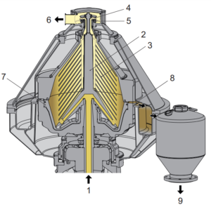
1. Inlet
2. Distributor
3. Disc stack
4. Impeller
5. Hermetic seal
6. Liquid phase outlet
7. Sliding bowl bottom
8. Solids discharge ports
9. Solids outlet from cyclone
Technical data
Performance data
| Maximum capacity | DN80: 550 hl/h (470 bbl/h)
DN100: 850 hl/h (725 bbl/h) |
| Maximum motor power | 55 kW (73.8 HP) |
Connections
| Feed inlet | DIN 11851 DN80/100 |
| Product outlet | DIN 11851 DN80/100 |
| Solids outlet | DIN Flange DN200 |
Material data
| Bowl body | Stainless steel, EN 1.4418 |
| Frame top part | Stainless steel 316, EN 1.4401, ASTM S31600 |
| Gaskets (product wetted) | NBR and EPDM, FDA approved materials |
| Piping | Stainless steel, AISI 304 |
| Frame and cabinets | Stainless steel, AISI 304 |
Weights
| System incl. separator, bowl and motor | 3200 kg (7055 lbs) |
| Bowl | 800 kg (1764 lbs) |
Dimensional drawing
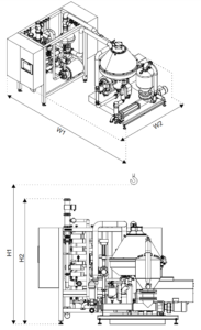
Dimensions
| H1 (minimum lifting height) | 3000 mm (9 ft 10 1/8 inches) |
| H2 | 2045 mm (6 ft 8 1/2 inches) |
| W1 | 3500 mm (11 ft 5 13/16 inches) |
| W2 | 2450 mm (8 ft 7/16 inches) |