Alfa Laval Unique RV-ST Regulating Valve
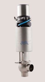
Unique RV-ST is the third generation of Alfa Laval single seat regulating valves designed to meet the highest process demands of hygiene and safety. Built on a well-proven, platform from an installed base of more than one million valves, it is ideal for high volume, sanitary liquid processing applications where precision control of flow rate or pressure is required.
Working principle
The valve is remote-controlled by a digital electro-pneumatic process controller. It has few and simple moveable parts which results in a very reliable valve.
Technical Data
Max. product pressure: . . . . . 10 bar (1000 kPa).
Min. product pressure: . . . . . Full vacuum.
Temperature range: . . . . . . . . 10°C to +140°C (EPDM).
Air pressure: . . . . . . . . . . . . 5 – 7 bar (500 to 700 kPa).
Positioner data
Material: . . . . . . . . . . . . . . . PPS, stainless steel
Cover: . . . . . . . . . . . . . . . . PC
Seals: . . . . . . . . . . . . . . . . EPDM
Supply voltage: . . . . . . . . . . 24 VDC +/- 10%
Working temperature: . . . . . . 0 to 55 °C
Push-in fittings: . . . . . . . . . . ø6mm or 1/4”
Protection class: . . . . . . . . . IP65 and IP67
Position detection module: . . . Contact-free, wear-free
Communication: . . . . . . . . . . Analog
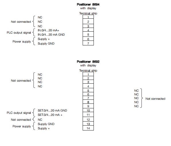
8692 Positioner – Top control with display
Setpoint setting: . . . . . . . . . 0/4 to 20mA and 0 to 5 5/10V
Output resistance: . . . . . . . . 0/4 to 20 mA: 180Ω
0 to 5/10V: 19Ω
Power consumption: . . . . . . < 5W
Cable gland: . . . . . . . . . . . . 2xM16x1,5 (cable-ø10mm)
Max. wire diameter . . . . . . . . 1.5 mm2
Physical Data
Product wetted steel parts: . . .1.4404 (316L)
External finish . . . . . . . . . . . .Semi-bright (blasted)
Internal finish . . . . . . . . . . . .Bright (polished), internal Ra < 0.8 µm
Other steel parts: . . . . . . . . .1.4301 (304)
Plug seal: . . . . . . . . . . . . . .EPDM
Other product wetted seals: . .EPDM (standard)
Other seals: . . . . . . . . . . . . .NBR
Valve Body Combinations
(IMAGE)
8694 Positioner – Basic control without display
Setpoint setting: . . . . . . . . .0/4 to 20mA
Output resistance: . . . . . . . .180Ω
Power consumption: . . . . . .< 3,5W
Cable gland: . . . . . . . . . . . .2xM16x1,5 (cable-ø10mm)
Max. wire diameter . . . . . . . .1.5 mm2
Standard design
Designed to deliver years of reliable performance, it features a broad selection of stainless steel, tapered valve stems along with the Unique actuator to ensure an outstanding degree of precise product control. Rugged and long-lasting plastic stem bushings eliminate metal-to-metal galling. The stems are threaded to the actuator shaft, eliminating the coupling between the stem and the actuator, thereby ensuring proper alignment. The plug seal is a standard seal used for the entire Unique Series. Bushings at the end of the actuator cylinder support the stem and ensure perfect alignment.
Other valves in the same basic design
- Sanitary Unique Single Seat
- Standard valve
- Reverse acting valve
- Long stroke valve
- Manually operated valve
- Aseptic valve
Options
a. Male parts or clamp liners in accordance with required standard
b. Product wetted seals in HNBR or FPM
c. Maintainable actuator
d. External surface finish blasted
e. Optional plug seal: HNBR or FPM
Note!
For further details, see instruction ESE02127
Pressure drop/capacity diagrams
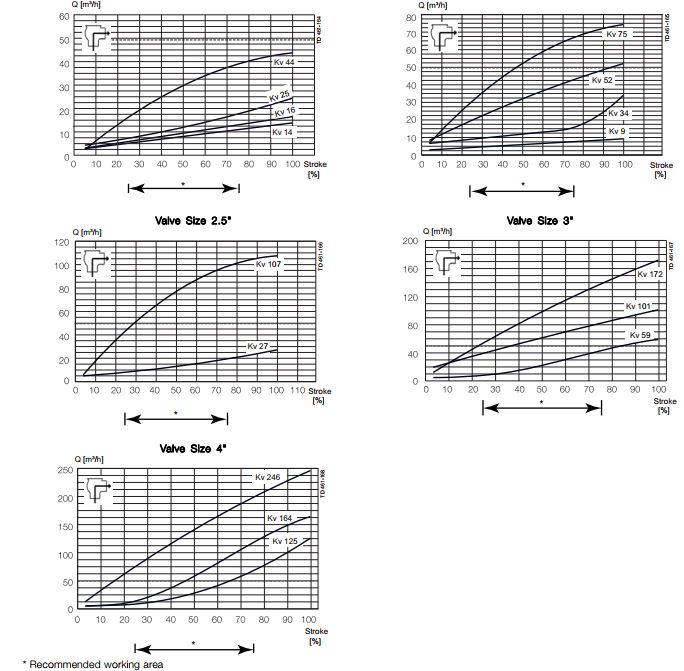
Note!
For the diagrams the following applies:
Medium: Water (20° C)
Measurement: In accordance with VDI 2173
——– (dotted line) = Kv 49
Alfa Laval recommends max. flow velocity in tubing and valves to be 5 m/sec.
Pressure data
Table 1 – Shut-off valves
Max. pressure in bar without leakage at the valve seat
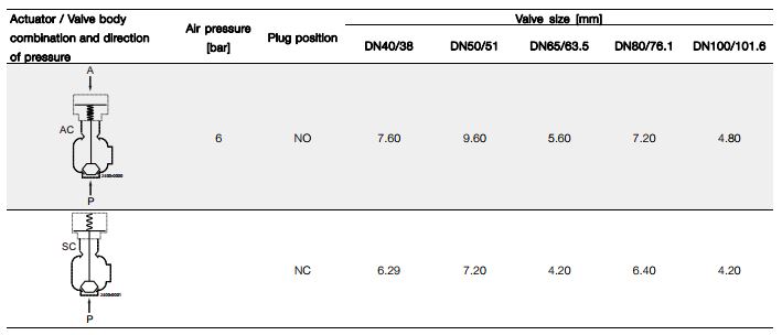
A = Air
P = Product pressure
AC = Air closes
SC = Spring closes
Valve Sizing
Flow Coefficients (Kv)
The following formula and flow coefficient values enable you to select the correct regulating valve for your application.
Formula for water and other products with a specific gravity equal to 1.0:
![]()
Formula for products with a specific gravity other than to 1.0:
![]()
Where:
Q =Product flow rate in m3 per hour
SG =Specific gravity of product
∆ P = Pressure drop across valve in bar
(inlet pressure minus outlet pressure)
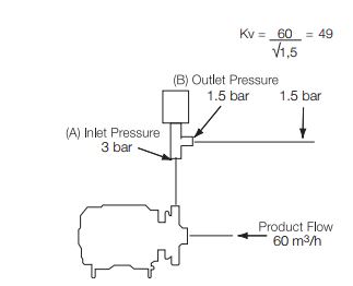
Example of Kv Calculation:
Determine the proper size valve for 60 m3 per hour of water.
Inlet pressure of 3 bar
Outlet pressure of 1,5 bar
Solution: Inlet pressure (A) minus outlet pressure (B):
∆ P = 3 bar – 1,5 bar = 1,5 bar
How to Use Data to Select Valve Size
After the Kv factor for a specific application has been calculated,
locate the factor on the following page. Choose the curve closest
to the 50% stroke.
Using the above example, refer to the chart on the previous page you
will find that the Kv factor (49) is marked on the chart. You will find
that a 2″ valve crosses 1 Kv curve, 2½” 1 curve, 3″ 3 curves and 4″ 3
curves. The correct valve size to use is 2″ because Kv 49 crosses the
curve closest to the optimum operating point 50%. Alternatively the
4″ valve is also close to the 50%.
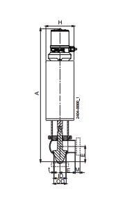
Dimensions (mm)
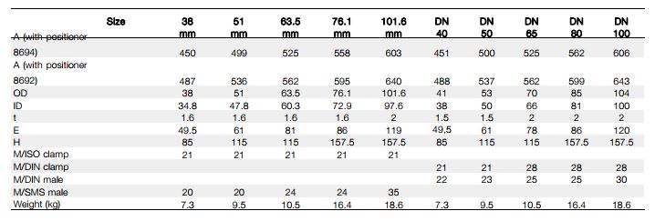
Air Connections Compressed air:
R 1/8″ (BSP) internal thread for actuator
Electrical connections