APV / SPX Double Seat Mix Proof D4 Series Valves
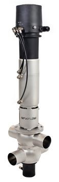
The next generation of mix proof valve technology is the result of continued development from both APV™ and Waukesha Cherry-Burrell™ process technologies. Used for the reliable separation of dissimilar fluids, the D4 Series helps fulfill today’s customer demands for production flexibility, increased productivity, rapid return on investment (ROI), and improved product quality across the Food & Beverage, Dairy, Personal Care and Brewing process industries.
High value, Low life cycle costs:
- Tiered model range helps to increase ROI and align with customer budgets
- “All In” standard features provide exceptional value
- Reduced inventory costs with same seal kit used on multiple size ranges: DN40-DN65 (1.5”-3.0”) and DN80-DN100 (4.0”)
- Reduced CIP losses improve cost savings
- Low air consumption and air supply requirements
- Long housing ports ease manifold building
- Integrated shaft seal flush reduces need for external piping
- Replacement insert available to easily upgrade existing installations
Reliable performance:
- Fully balanced design helps to prevent hydraulic blocking, withstand pressure spikes, and enables flexible flow direction without slamming
- Light overall weight helps support handling without lifting tools
- Slim stainless actuator is fully enclosed to prevent fluid ingress
- Range of control units and bus communication for automated operation
- No compressed air needed for removal and servicing
Cleanability:
- Designed to the latest hygienic standards
- Standard cavity spray cleaning
- Extensive cleaning of product contact seals
Benefits of D4 Series Valves
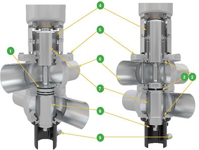
| Valve Type | Feature | Benefit | |
| D4 | 1 | Radial seal design for reduced losses of product fluids during switching | Product cost savings Cleaner operating environment |
| DA4 | 2 | Integrated upper and lower shaft seal and balancer flushing | Extensive cleaning of product contact surfaces |
| DA4 | 3 | Metal orifices control CIP flow during seat lift | Reduces chemical and water loss consumption |
| D4 and DA4 | 4 | Open yoke design | Reduces heat transfer from product zone into actuator Provides visual leak detection of damaged shaft seal Safety guard provided to reduce pinch points |
| 5 | Bolted flange connection for housing/insert | Heavy duty, secure connection Reliable and controlled assembly and disassembly of valve insert |
|
| 6 | Long ports to ease manifold building | Helps to reduce spool pieces and welds to ease manifold building | |
| 7 | Balanced upper and lower shafts (as standard) | No hydraulic blocking Resistant against pressure spikes Flexibility in either flow direction through the valve (top-to-bottom or bottom-to-top) without water hammering |
|
| 8 | Large separation cavity drain port | Less product risk and guards against pressure build up which could cause cross-contamination. | |
| 9 | Flush cavity spray fixed connection (as standard) | Enhanced cleaning Removes residual media in separation cavity when full CIP is not readily available Hard-piped flush can be used without need to be removed during valve maintenance |
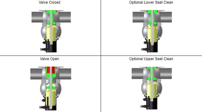
Theory of Operation
Double seat mix proof valves are used to efficiently process two different fluids (typically product and CIP) through the valve simultaneously. The mix proof design has two seats which isolate the upper and lower pipe lines when the valve is in the fail-safe closed position.
The atmospheric vent cavity in between the seats creates a path for any leakage should the seals fail as well as a drain for CIP solution during seat cleaning. An external CIP spray flush is included to provide enhanced cleaning of the leakage and vent cavity while the valve is closed or open during production.
Technical Data
| Sizes | DN 40 – 100 OD Tube 1.5” – 4” others on request |
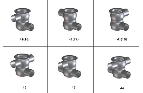
| Housing Types | 41, 42, 43, 44 |
| Product-Wetted Parts | 1.4404/AISI 316L Other stainless steel parts 1.4301/AISI 304 |
| Seal Materials | EPDM, HNBR, FPM All seals comply with the FDA requirements |
| Surfaces | Inside: electropolished Ra 0.8 µm (32 µ-in) with Electropolish Outside: Glass-blasted, satin finish |
| Product Pressure | 10 bar (145 psi) |
| Max. Temperature | EPDM & HNBR: 135ºC/275ºF (for short time 140ºC/284ºF) FPM 135ºC/275ºF (not to be used for steam) |
| Sterilisation Temperature | EPDM & HNBR: (for short time) 140ºC/284ºF |
| Required Air Pressure | 5 bar (73 psi), valve normally closed |
Housing Combinations
Shut-off Valves
Control Units

CU4 Series
Features and Benefits
- Automated control and position monitoring for reliable processing
- Reduces compressed air and electrical connections
- Helps reduce external solenoid valve cabinets
- Accelerates valve response time
- Reliability and long service life – robust clamp connection, reinforced stainless steel air coupling threads to avoid air leakages, and water tight seals
- Ease of operation – contains manual override solenoids and adjustment screw to throttle air flow to actuator to ensure optimal opening and closing
- Clarity – clear and bright indication of valve position – 5 diodes in LED panel and convenient location
- Standardization – same control top used on various SPX FLOW valve lines, offers common look and controls interface
- IP67 (NEMA 6) washdown rating
| CONNECTOR OPTIONS S/O Cord Grip for hard wire (std) |
POSITION INDICATION 2 internal feedback sensors for valve open/valve closed position detection |
| INTERFACE OPTIONS 24V DC Direct Connect AS-i Field Bus Card |
SOLENOID VALVES 24V DC Select 1 (non seat lift) or 3 Solenoids (seat lift) |
D4 Dimensions

| Dimensions mm | A | A1 | B | øDi | øDa | F | H | L | L1 | X* | Y* |
| DN | |||||||||||
| 40 | 483 | 566 | 120 | 38 | 41 | 125 | 63 | 666 | 749 | 820 | 200 |
| 50 | 487 | 570 | 126 | 50 | 53 | 125 | 75 | 688 | 771 | 830 | 218 |
| 65 | 495 | 578 | 134 | 66 | 70 | 125 | 91 | 720 | 803 | 840 | 242 |
| 80 | 583 | 666 | 146 | 81 | 85 | 142.5 | 106 | 835 | 918 | 930 | 274 |
| 100 | 593 | 676 | 156 | 100 | 104 | 142.5 | 125 | 874 | 957 | 940 | 303 |
| INCH | |||||||||||
| 1.5 | 485 | 568 | 119 | 34.8 | 38.1 | 125 | 63 | 667 | 750 | 820 | 197 |
| 2.0 | 488 | 571 | 125 | 47.6 | 50.8 | 125 | 75 | 688 | 771 | 830 | 216 |
| 2.5 | 492 | 575 | 131 | 60.3 | 63.5 | 125 | 85.3 | 708.3 | 791.3 | 840 | 233 |
| 3.0 | 498 | 581 | 137 | 72.9 | 76.1 | 125 | 97.9 | 732.9 | 815.9 | 850 | 251 |
| 4.0 | 594 | 677 | 155 | 97.6 | 101.6 | 142.5 | 125 | 874 | 957 | 840 | 301 |
D4 SL Dimensions

| Dimensions mm | A | A1 | B | øDi | øDa | F | H | L | L1 | X* | Y* |
| DN | |||||||||||
| 40 | 524 | 607 | 120 | 38 | 41 | 125 | 63 | 707 | 790 | 870 | 200 |
| 50 | 528 | 611 | 126 | 50 | 53 | 125 | 75 | 729 | 812 | 880 | 218 |
| 65 | 536 | 619 | 134 | 66 | 70 | 125 | 91 | 761 | 844 | 890 | 242 |
| 80 | 618 | 701 | 146 | 81 | 85 | 142.5 | 106 | 870 | 953 | 980 | 274 |
| 100 | 628 | 711 | 156 | 100 | 104 | 142.5 | 125 | 909 | 992 | 990 | 303 |
| INCH | |||||||||||
| 1.5 | 526 | 609 | 119 | 34.8 | 38.1 | 125 | 63 | 708 | 791 | 870 | 197 |
| 2.0 | 529 | 612 | 125 | 47.6 | 50.8 | 125 | 75 | 729 | 812 | 880 | 216 |
| 2.5 | 534 | 617 | 131 | 60.3 | 63.5 | 125 | 85.3 | 750.3 | 833.3 | 900 | 233 |
| 3.0 | 540 | 623 | 137 | 72.9 | 76.1 | 125 | 97.9 | 774.9 | 857.9 | 900 | 251 |
| 4.0 | 629 | 712 | 155 | 97.6 | 101.6 | 142.5 | 125 | 909 | 992 | 990 | 301 |
DA4 Dimensions
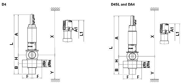
| Dimensions mm | A | A1 | B | øDi | øDa | F | H | L | L1 | X* | Y* |
| DN | |||||||||||
| 40 | 589 | 672 | 120 | 38 | 41 | 125 | 63 | 772 | 855 | 930 | 200 |
| 50 | 593 | 676 | 126 | 50 | 53 | 125 | 75 | 794 | 877 | 940 | 218 |
| 65 | 601 | 684 | 134 | 66 | 70 | 125 | 91 | 826 | 909 | 950 | 242 |
| 80 | 678 | 761 | 146 | 81 | 85 | 142.5 | 106 | 930 | 1013 | 1030 | 274 |
| 100 | 688 | 771 | 156 | 100 | 104 | 142.5 | 125 | 969 | 1052 | 1040 | 303 |
| INCH | |||||||||||
| 1.5 | 588 | 671 | 119 | 34.8 | 38.1 | 125 | 63 | 770 | 853 | 930 | 197 |
| 2.0 | 594 | 677 | 125 | 47.6 | 50.8 | 125 | 75 | 794 | 877 | 940 | 216 |
| 2.5 | 598 | 681 | 131 | 60.3 | 63.5 | 125 | 85.3 | 814.3 | 897.3 | 950 | 233 |
| 3.0 | 604 | 687 | 137 | 72.9 | 76.1 | 125 | 97.9 | 838.9 | 921.9 | 960 | 251 |
| 4.0 | 689 | 772 | 155 | 97.6 | 101.6 | 142.5 | 125 | 969 | 1052 | 1050 | 301 |
*Minimum installation and valve insert removal dimensions