
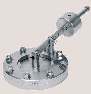
Alfa Laval SB Anti Vacuum Valve
The Anti Vacuum Valve is used for minimizing the risk of implosion of tanks exposed to vacuum e.g. during emptying, cool-rinsing after hot-cleaning or caustic cleaning in a CO2 atmosphere. The Anti Vacuum Valve can be applied on any closed tank.
Working principle
The Anti Vacuum Valve is delivered with counter weight set and locked for an individual opening vacuum to suit the tank design data. When a vacuum in the tank is lower than the preset opening value, the valve opens and lets in atmospheric air.
Technical Data
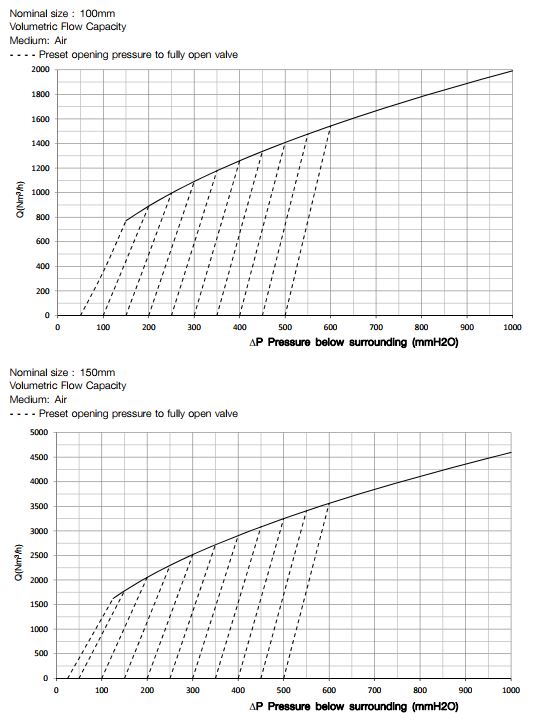
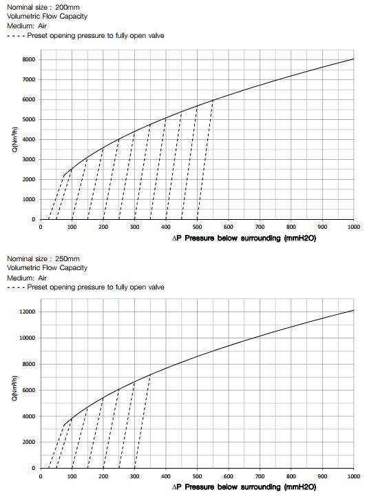
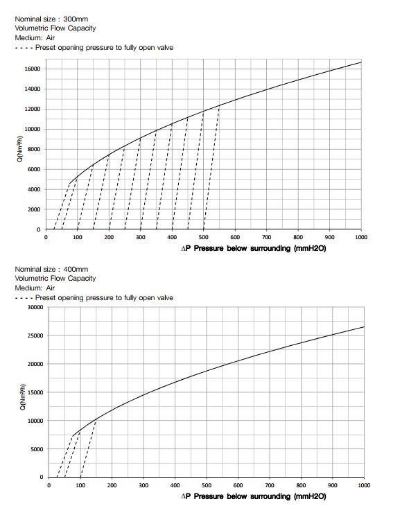
Nominal Size Opening pressure range (∆P) Allowable pressure PS
100 mm 50 – 500 mmH2O 6 bar
150 mm 25 – 500 mmH2O 6 bar
200 mm 25 – 500 mmH2O 6 bar
250 mm 25 – 300 mmH2O 4 bar
300 mm 25 – 500 mmH2O 4 bar
400 mm 25 – 100 mmH2O 4 bar
Physical Data
Materials
Product wetted steel parts: EN 1.4404 (AISI 316L) with 3.1 cert.
Product wetted steel surfaces: Surface roughness Ra<0.8 µm
Product wetted seals: EPDM
Product wetted polymers: PEEK
Other steel parts: EN 1.4307 (AISI 304L)
Standard design
The Anti Vacuum Valve is available in two versions:
- Integrated in a SCANDI BREW® tank top system
- Mounted on its own counter flange
Compliance Pressure Equipment Directive 2014/68/EU of the European Community, Fluida Group II
The advantages of an integrated Anti Vacuum Valve are lower initial costs, superior hygiene and smaller area required for seat valve. The size and setting of the Anti Vacuum Valve is based on the tank vacuum rating, maximum emptying speed, cleaning procedure and process requirements. The Anti Vacuum Valve is produced in a hygienic and robust design. Heating elements are available for valves exposed to sub-zero temperatures. It is very important to note that if the cleaning procedure includes hot-cleaning, the valve should be dimensioned with the purpose of preventing implosion from the vacuum that appears when flushing with cold water.
The Anti Vacuum Valve should be seated horizontally. An inclination of max. 5° is acceptable but the lever arm must then point into the center of the cylindro-conical tank top.
Options
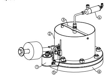
Pos. 1: Force opener: force-opening during valve seat cleaning
Pos. 2: Splash guard: containing CIP liquid during valve seat cleaning
Pos. 3: CIP Nozzle: for cleaning valve seat
Pos. 4: CIP closing valve: applying CIP liquid
Pos. 5: Proximity sensor: for operation detection
Pos. 6: Welding flange: for installation
Heating elements: for valves exposed to sub-zero temperatures
Cleaning In Place (CIP)
The Anti Vacuum Valve is cleaned, when closed, by the tank cleaning head, but this will not include the valve seating. To include the valve seating in the cleaning cycle, there are two options:
CIP Kit 1 – Force opener; splash guard
The valve is force-opened during tank CIP. The cleaning of valve seat is dependent on cleaning jets from the tank cleaning head. Any CIP liquid escaping the tank is contained by the splash guard and drains back in to the tank.
CIP Kit 2- Force opener; splash guard; CIP nozzle; CIP closing valve
The valve is force-opened during tank CIP. The cleaning of valve seat is performed by the CIP nozzle. All CIP liquid from the CIP nozzle is contained by the splash guard and drains back in to the tank. NOTE: Applying any of above CIP options provides that the tank is pressureless at the moment of force opening the Anti Vacuum Valve.
Integrated Valve
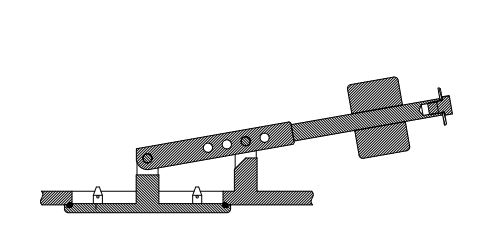
Flange Mounted Valve

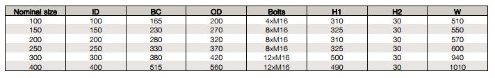
Interface requirements (mm)
Keeping you processing
For more information about our products and services please get in touch!

JAMIE WETHERILL
Internal Sales Manager
Call: 01777 712101
Email: jamie.wetherill@moodydirect.com